Finding The Time
Building a DIY GPS-Disciplined Oscillator (GPSDO) for a Stratum-1 NTP Server - Part 1⌗
Over the past few weeks I’ve been experimenting with building a Stratum-1 NTP server and, as often happens with hobby electronics projects, the scope has grown significantly.
The original goal was fairly straightforward: use an ESP32 and GPS receiver to provide accurate network time to my home lab. The project started with a HackerBox GPS module and quickly evolved into a deep dive into NTP, PPS timing signals, GPS receivers, oscilloscopes, DACs, and oven-controlled crystal oscillators (OCXOs).
The First Prototype⌗
The initial design consisted of:
-
ESP32 development board
-
Quectel L80-R GPS receiver
-
PPS (Pulse Per Second) timing signal from GPS
-
Web-based monitoring interface
-
NTP server implementation
After a fair amount of troubleshooting—including GPS lock issues, serial pin configuration mistakes, and discovering a shared PPS/TFT backlight pin on the project board—I was eventually able to obtain a GPS lock and serve NTP responses across my network.
Testing with w32tm showed the server responding correctly, although timing accuracy still had room for improvement.
Learning About PPS and NTP⌗
One of the biggest lessons from this project was understanding how NTP actually works.
Before starting, I assumed an NTP server simply distributed the current time. In reality, accurate timekeeping relies heavily on precise timing measurements and stable clock sources.
The GPS receiver provides two important outputs:
-
NMEA data containing date and time information
-
PPS (Pulse Per Second), a highly accurate timing pulse aligned to UTC
The PPS signal is what allows a system to achieve Stratum-1 accuracy.
The Rabbit Hole: GPSDOs⌗
While researching timing accuracy, I discovered GPS-disciplined oscillators (GPSDOs).
A GPSDO combines:
-
GPS timing signals
-
A highly stable oven-controlled crystal oscillator (OCXO)
-
A control loop that continuously corrects oscillator drift
The GPS signal provides long-term accuracy while the OCXO provides excellent short-term stability.
This is the same principle used in professional timing equipment, telecommunications infrastructure, and laboratory frequency references.
New Hardware⌗
To explore this further, I recently added:
-
10 MHz OCXO module
-
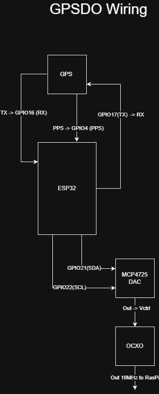
MCP4725 12-bit DAC
-
ESP32 control interface
-
Oscilloscope measurements of the oscillator output
The DAC will eventually allow the ESP32 to make tiny adjustments to the OCXO control voltage based on timing measurements from the GPS PPS signal.
The result should be a disciplined 10 MHz reference that can be used to generate an extremely stable PPS signal for a future Raspberry Pi-based Stratum-1 NTP server.
Current Status⌗
The OCXO and DAC hardware are now wired together and communicating through the ESP32. The oscillator is powered and producing a clean 10 MHz output, and the DAC is connected into the OCXO’s frequency calibration circuit.
I’m currently waiting for a replacement GPS module after accidentally destroying the pads on the original L80-R while attempting to remove it from a development board. Fortunately, replacement modules are inexpensive and should provide an opportunity to rebuild the GPS side of the project with a cleaner design.
!
What’s Next?⌗
The next milestones are:
-
Verify DAC control of the OCXO
-
Integrate the new GPS receiver
-
Measure PPS timing accuracy
-
Implement a GPS discipline control loop
-
Generate a clean PPS signal from the disciplined oscillator
-
Feed that PPS signal into a Raspberry Pi running Chrony
The ultimate goal is a home-built GPS-disciplined Stratum-1 NTP server capable of providing highly accurate time to my entire home lab.
Whether it ends up being more educational than practical remains to be seen, but I’ve already learned far more about GPS, timing systems, oscillators, and NTP than I ever expected when I started.
And honestly, that’s usually the best kind of project.